Air Bearing Fundamentals
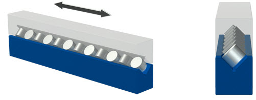
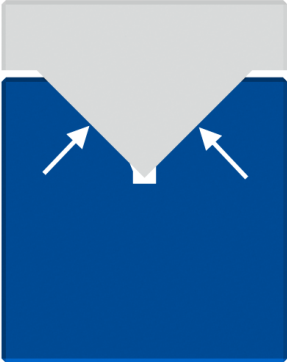
As with conventional bearings, air bearings constrain the relative motion of a desired object to one or more axes. Nearly every conventional bearing has an analogous air bearing form. For the moment, we will examine a basic linear bearing with cross rollers making contact within a v-groove.
The lower blue rail is fixed while the upper rail is allowed to move left and right as it makes contact with the rotating rollers.
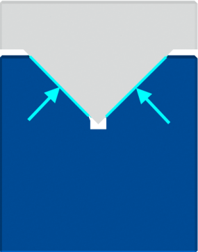
The air bearing analog is shown below. The rollers are replaced by a film of air (shown light blue) and the upper rail (shown transparent) now mates into the v-groove.
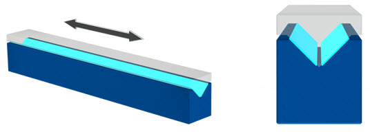
Here is how it works:
- When the air bearing is not energized, the mating surfaces are in direct contact.
- Through either relative motion or an external pressure source, a very thin layer of fluid (light blue line), in this case a gas or air becomes pressurized between the two static objects.
- Because the gap is kept small by a preload force, the air escapes to atmosphere slowly and therefore builds pressure.

- When the pressure becomes large enough, the resulting force causes the upper element to move a small distance away from the stationary element until static equilibrium is reached.

- This air gap distance is determined by the amount of total load applied and fluid pressure within the separation; a larger pressure results in a larger separation.
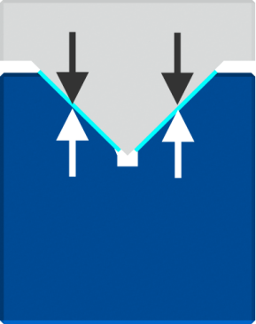
At this point, due to the lack of contact between the mating surfaces, frictionless, zero-wear motion is achieved. Knowing the correct air gap during installation and operation is critical for proper performance. Our gap sensing air bearings provide an efficient and sometimes only method for measurement of the air film thickness.
Air bearings can produce very high accuracy motion- much higher than conventional bearings like the cross roller example above. With typical straightness errors of less than 0.1 microns / 100mm and rotational accuracies of less than 0.02 microns, air bearings stand in a class by themselves.
Source of accuracy
As the roller of the mechanical bearing described above follows the imperfections of the v-groove, noise is generated causing errors in the motion straightness. Air bearings do not have direct contact with the riding surface and therefore do not experience this problem. Indeed, the resulting motion accuracy for the air bearing is an average of all the imperfections of the mating surfaces. Changes in riding height are caused by deviations of the entire region local to the bearing face.
Source of repeatability
Due to the lack of wear, accuracy is maintained throughout the entire life of the bearing and is the reason air bearings exhibit very high repeatability. In many cases, air bearings provide motion repeatability of less than 0.02 microns with the limiting factor most often the precision of the positioning system. This characteristic allows machine tool builders using linear stages to create a position error map for a given axis. The measured straightness errors are added to the machine control algorithm which compensates the position with one or more of the orthogonal axes. This method makes manufacturing stages somewhat less costly due to a relaxation of the form tolerances of the guideways.
High speed operation
When mechanical bearings for high speed applications are required, designers may often choose ball or roller configurations due to their lower friction. High speed operation is limited as a result of heat generation and wear of the mating surfaces. In addition, high acceleration of the stage can cause slipping or dragging of the rollers or creeping of the cage used to separate the balls or rollers and increasing the load worsens all of these conditions. Fortunately, these negative aspects are not present when using air bearings. Due to the low viscosity of gases like air, heat generation typically does not occur until speeds reach 40-60 meters per second (over 100 miles per hour). This effect can be by controlled by changing the bearing surface geometry or increasing the air gap. Stages with powerful linear motors have been manufactured with accelerations greater than 14g. All of these advantages are equal whether the air bearing is at zero load or maximum load.
As stated above, either relative motion or an external pressure air source can cause the gap to become pressurized. This fact divides air bearings into two general classes:
- Aerodynamic (requiring relative motion to generate air film)
- Aerostatic (requiring an external pressure source to generate air film)
What is an aerodynamic air bearing?
In the case of aerodynamic bearings, also known as self-acting bearings, special features may be manufactured into the mating surfaces which act like a small pump. At rest, the mating surfaces may be in direct contact. Relative motion forces the air molecules from atmosphere into the gap where they begin to accumulate with increasing pressure. As the speed increases, a velocity induced pressure gradient forms across the clearance. The increased pressure between the surfaces creates the load carrying effect. The load capacity is dependent on the speed at which the surface moves and therefore at zero speed, the air bearing supports no load.
In general, aerodynamic bearings suffer from decreased load carrying capacity. In addition, the zero-load at zero speed effect causes starting and stopping friction and may result in some wearing of the air bearing surfaces. Notwithstanding some of the disadvantages, self-acting bearings have found widespread industrial use. The most ubiquitous example may be the magnetic read/write heads of a disk-based hard drive memory storage device. In this case, a flat thrust-load carrying air film is created between the disk surface and the head. An armature positions and lightly preloads the flat head against the surface while a motor provides relative motion by spinning the magnetic disk. As pressure builds, the head elevates above the disk surface. As hard drive technology has improved, the distance at which the air bearing head flies has been reduced to as small as 3 nanometers. This gap is about 30,000 times thinner than the average thickness of a sheet of notebook paper. Small air gaps present fabrication difficulties which are discussed in the Manufacturing Challenges section below.
However, large air gaps can be designed for if the relative velocity of the mating surfaces is sufficiently high. As the velocity increases so does the pressure. With this increase in pressure, the separation between the mating surfaces can be increased. In fact, hypersonic relative velocities of flat aerodynamic pads have successfully been built supporting thousands of pounds. This type of bearing could find use in the proposed Hyperloop concept.
Again, the aerodynamic air bearing's principle advantage is its ability to act without an external pressure source. The load capacity is limited by the area of the bearing and the relative velocity of the mating surface. Therefore, aerodynamic air bearings can be applied in limited cases:
- Where the application requires lack of an external pressure source
- Where the application can provide enough relative velocity to generate lift for a given size of the bearing
Aerostatic air bearing principles
Applications which can allow an external pressure source to supply air to the bearing do not suffer the negative effects of surface wear at the start and/or end of motion. Air bearings operating in this way are described as aerostatic. This type will support its entire design load at zero or high speed with zero stiction and wear. At rest, the bearing mating surfaces are in direct contact with a load applied. Commonly, an attached air tube delivers pressurized air or other gas to the bearing housing. Features inside the bearing direct the air to the gap interface through different methods further explained below. As described previously, due to the small clearance maintained by the applied load, the air molecules cannot escape quickly enough from between the mating surfaces to atmosphere. This restriction causes an accumulation of pressure which continues to build until the resulting force begins to push apart the mating surfaces. The gap increase persists until a balance of inlet pressure and air flow restriction is created. The air bearing now exhibits frictionless motion.
The load capacity of aerostatic air bearings is limited only by the supply pressure and the strength of the mechanical components. Remarkably, when designed correctly, air bearings can support multi-ton loads without friction or wear of the mating surfaces.
The manner in which the pressurized gas is admitted to the gap further divides the aerostatic category into a few different types:
- Porous surface
- Partial porous surface
- Discrete Orifice feeding
- Slot feeding
- Groove feeding
The diagrams below show some basic configurations of the inlet methods for air bearings with an approximated pressure profile for each air film.
Porous Surface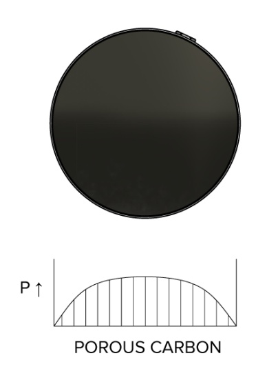
The air flows to the gap and is restricted by a porous material such as carbon, bronze, or other material. This type of bearing provides the best pressure distribution and therefore has a slightly higher load capacity and stiffness. In the case of porous carbon, accidental contact of the mating surfaces during relative motion will not cause a large degree of performance loss of the bearing. However, due to the manufacturing process of the porous material, this type of bearing may emit very small particles during operation. This may not be desirable in cleanroom environments like those used in semiconductor wafer fabrication.
Partial Porous Surface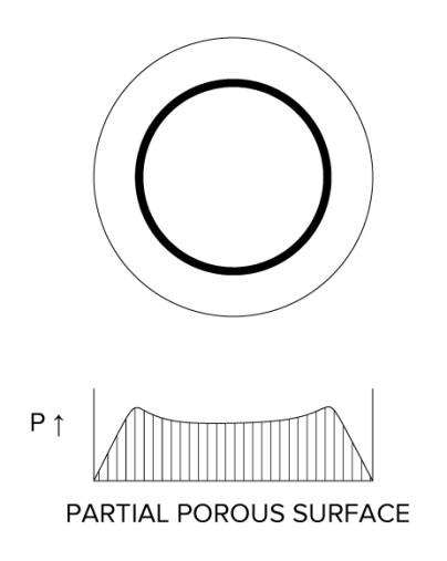
A portion of the air bearing surface has a porous material allowing air to flow. This combination of a solid and porous surface can provide higher damping during dynamic conditions. The inlet ring shown here provides an even source of air distribution. Properly controlling the permeability of the porous material over the proportionately small area is difficult and often requires a valve or other restrictor integrated within the housing to adjust the flow rate.
Discrete Orifice Feeding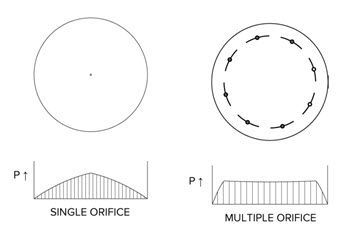
One or more small holes are featured at the face of the air bearing which restrict air flow to the film. This method can provide very small flying height variations from bearing to bearing. Flat air bearings utilizing orifice may have tilts of less than 0.1 microns. Although they are not as robust as the porous carbon type, orifice air bearings can be made to have fewer than five 0.1 micron particle emissions per minute. The relative simplicity of orifice type bearings often results in the lowest manufacturing costs.
Slot feeding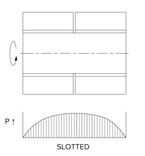
This type of air inlet is similar to orifice air bearings but in place of a small hole is a rectangular slot. Often used in cylindrical journal air bearings, this type of air distribution is more uniform and more calculable than orifice bearings. Slot fed air bearings have higher stiffness at high eccentricity positions of the journal shaft. They tend to be more costly to manufacture in small quantities.
Groove Feeding
Also utilized in cylindrical journal air bearings, multiple small grooves are manufactured axially into the bearing surface leading from an air source volume near the center of the journal. This method can result in very high stiffness and symmetrical air flow distribution within the film but it can be more costly than orifice or slot feeding air bearings.
NOTE: There is no single best approach to feeding the air to the film. The choice depends on the application requirements and this is why we manufacture all of the types listed above in addition to some other types.
Performance Characteristics
Load capacity and stiffness are typical qualities to evaluate when considering selection of an air bearing. The load capacity is a function of the film pressure and the effective bearing surface area. The average film pressure is generally about 40 percent of the inlet pressure. Therefore the load capacity of a flat air bearing with one square inch of area operating at 80 psig inlet pressure is about 32 pounds (40% x 80 psig x 1 inch^2). Stiffness, also an important characteristic, is the bearings ability to resist changes in air gap with changes in load. For every square inch of a flat air bearings surface, there is about 100,000 lbs/inch stiffness. This means an air bearing with 10 square inches of area has about 1,000,000 lbs/inch stiffness. Both of these characteristics, including others like flow rate, are measured and recorded for each air bearing we produce.
What about hydrodynamic and hydrostatic bearings?
These types of bearings are similar to air bearings in operating principle except they use a liquid as the pressurized fluid. Sizes being equal, liquid film bearings have a higher load capacity and stiffness than gas film bearings due to the higher viscosity of the fluid. However, this causes more friction and heat. These bearings require a method to collect and recirculate the liquid as it exhausts from the film gap; air bearings may simply vent to atmosphere. For hydrostatic bearings, this recirculated liquid requires careful filtration after exposure to the surfaces used to collect the fluid. Proper designs allow for bleeding of the air within the liquid. Air entrapment within the inlet channels and supply tubing can migrate towards the film and cause performance issues.
When to use air bearings:
It is safe to say: air bearings are not suitable for all applications but when they are used effectively, each prescription has some common characteristics. Generally, it is advisable to use air bearings when one or more of the following is an application requirement:
- nanometric repeatability and/or accuracy
- frictionless motion
- zero stiction
- zero backlash
- zero wear of the mating surfaces
- high speed and high acceleration
- low or near-zero particle emission
Other advantages include: lack of oil-based lubricants for operation, no service maintenance, no “run-in” period, simplification over conventional bearings, improved damping in dynamic performance, improved machine efficiency.
When not to use air bearings:
(Why would a company trying to sell air bearings bring up this point?) In order for an application to succeed, it is important to fully understand the special requirements, characteristics and installation guidelines of air bearings. To that end, we often convince potential customers to utilize conventional bearings in order to satisfy the design requirements. With all the benefits they provide, air bearings are not a panacea of tribology.
Generally, do not use air bearings when the application:
- does not require near frictionless motion
- does not require high accuracy and repeatability
- involves environments where the air bearing surfaces may be exposed to oils or other sticky substances
- cannot allow for a pressure source in the case of aerostatic air bearings (externally pressurized)
- requires minimal performance after high overload conditions on the air bearing
- cannot provide for accurate machining of the mating surface in the case of flat or cylindrical bushing air bearings
- requires high load capacity in a small design envelope
The choice to utilize air bearings in an application requires careful consideration and often the benefits are a result of sacrifices in the design. For example, ball bearings may not suffer performance immediately following an overload condition. However, an air bearing will tend to catastrophically fail with obvious signs like lockup or high friction. This could be good or bad depending on your point of view. Good: if an application is overloading the bearing, the designer would like to know at once of this problem in order to correct the design. Bad: if the application is overloading the bearing, some performance, although diminished, may be desirable.
Manufacturing challenges of air bearings
For proper performance, fluid film bearings require the gap to be small to allow pressure to build. For bearings using gases, this gap is on the order of only a few microns or about 25 to 50 times thinner than the diameter of a human hair. In addition, the bearing and mating surface geometry is usually controlled to less than one fifth of this gap. This accuracy requirement presents a manufacturing challenge. In order to produce spherical, cylindrical and planar surfaces with form tolerances of less than 10-20 millionths of an inch, specialized machinery and methods are needed. The standard to which measurement takes place is generally much higher than typically found in a quality inspection department. To that end, it is often necessary to employ temperature controlled environments, the use of vibration-isolated measuring platforms and clean room assembly workstations.
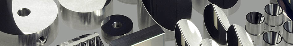
Materials
In order to manufacture air bearing surface geometries to sub-micron accuracy, rigid metals, ceramics or other similar materials often comprise the housing and/or static components. In addition, long-term material stability is an unconditional requirement if high repeatability is to be achieved. By no means an exhaustive list, the materials shown below have been used as air bearing components and surfaces.
- Hardcoated aluminum
- Steel, stainless steel
- Brass/bronze
- Glass
- Nickel
- Invar
- Macor
- PEEK
- Ceramic
- Graphite
- Carbon
- Granite
Design Configurations
The ways in which air bearings can be configured to constrain motion are numerous. A few arrangements are illustrated below to help form a basis of understanding. Parts which are intended to be stationary are shaded dark blue, while moving elements are shaded gray. Air gaps are indicated with light blue contours.
SINGLE SURFACE AIR BEARINGS
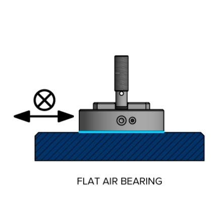
Flat thrust air bearing
The planar surface provides pure thrust load capacity and is a basic component of many linear stage assemblies. A portion of the surface can be used to include a vacuum pocket allowing for inherent preloading of the air film.
Spherical Air Bearing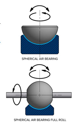
One single air bearing surface provides three frictionless axes of rotation. Five or six low-friction, mechanical rolling-element bearings would be required to achieve the same number of degrees-of-freedom. The spherical air bearing shown in the first diagram demonstrates the simplicity of the configuration while at the same time, providing continuous yaw and limited pitch and roll rotation. A deep capture of the rotating sphere results in higher side load capacity and bearing stiffness.
The second diagram shows that by changing the arrangement of how the payload is attached can result in full travel of the roll and yaw axes.
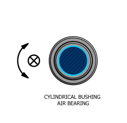
Cylindrical Bushing Air Bearing
An air bearing surface is formed between a cylindrical shaft and a mating air bearing bushing. The resulting linear and rotational motion is a cost effective solution. A segment of the bearing cylinder may be omitted resulting in an open radial pad.
SINGLE-AXIS ROTATING AIR BEARING SPINDLES
GHUS Air Bearing Spindle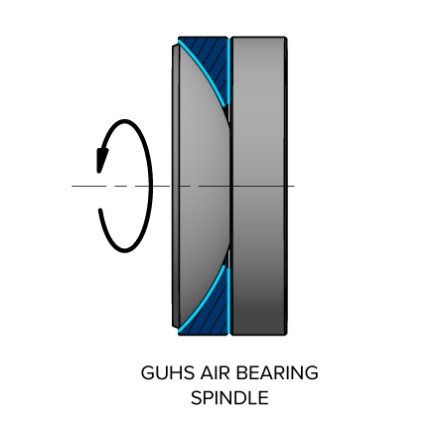
(General Utility Hydrostatic Spindle) Developed by Mr. Gordon Watt, this type of spindle utilizes a low-cost spherical bearing coupled to a thrust bearing. The simplicity is a result of the self-aligning nature of the sphere to the flat thrust plate.
Type-A Journal Air Bearing Spindle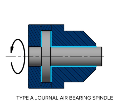
Popular in diamond turning machines, a singular cylindrical surface is joined with two perpendicular flat thrust surfaces.
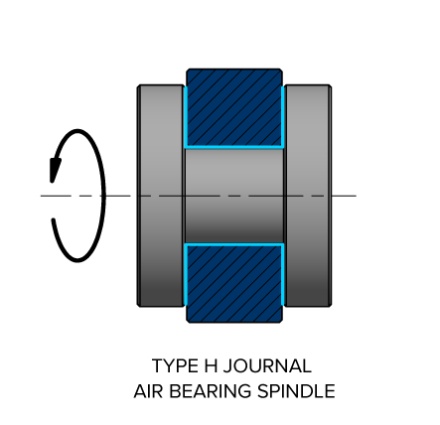
Type-H Journal Air Bearing Spindle
An all purpose spindle configuration, this bearing features two opposed thrust surfaces separated by a cylindrical air bearing surface.
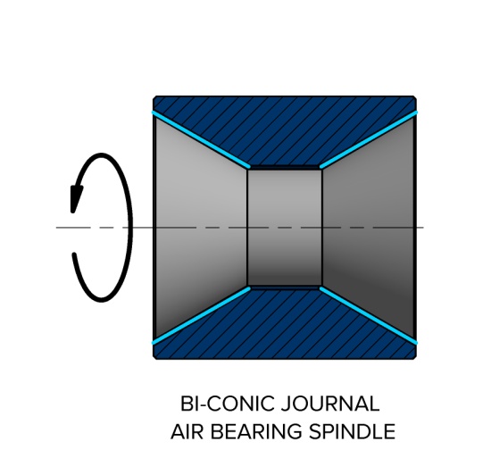
Bi-conic Air Bearing Spindle
Two opposing conical air bearing surfaces may or may not be joined to a central cylinder. The geometry of a cone is exploited to allow the thrust and radial forces to be supported by one air bearing surface on each end. This simplification can present manufacturing challenges maintaining the cone faces to be symmetrical and coaxial.
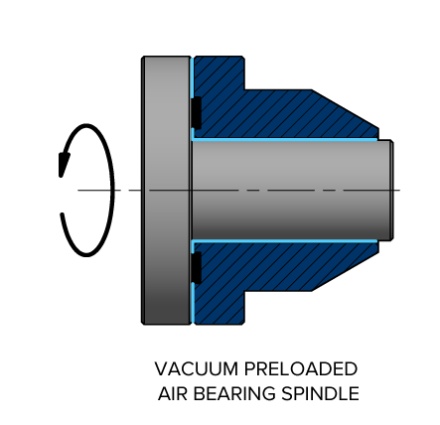
Vacuum Preloaded Air Bearing Spindle
Axial constraint is simplified by the use of vacuum within the rotating thrust plate. Additional interlocks and failsafe constraints are required to prevent operation without active vacuum.
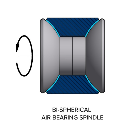
Bi-spherical Air Bearing Spindle
Without the cylindrical section as an air bearing surface as shown here, this design allows for misalignment of the two spherical surfaces. Upon assembly, the two flat surfaces will rotate to become parallel thus eliminating the need for high accuracy during machining of the position of the two spherical radii. Like the bi-conic spindle, thrust and radial forces are supported by only one air bearing surface on each end.
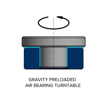
Gravity Preloaded Air Bearing Turntable
Air film preload is accomplished by using the weight of the rotor and thrust plate. Some high quality audio turntables utilize this design. A mechanical hard stop may be included to prevent disassembly of the bearing.
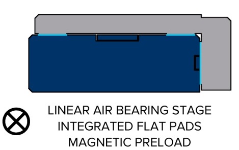
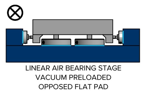
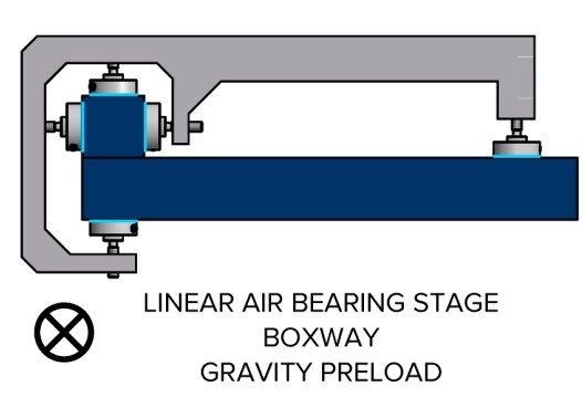
LINEAR STAGE ASSEMBLIES
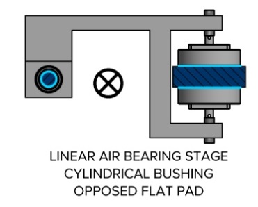
Cylindrical air bushing – Opposed Flat pads
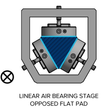
Opposed flat pads on triangular rail
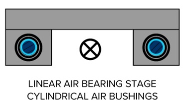
Dual cylindrical air bushings
Vacuum preloaded flat pads – opposed flat pads
Boxway flat pads – gravity preloaded pad
Integrated flat pads – magnetic preload